Power Solution Information
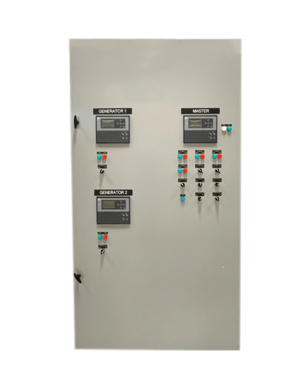
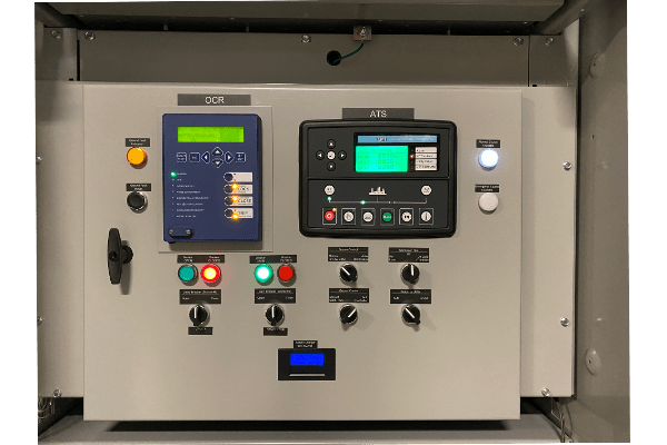
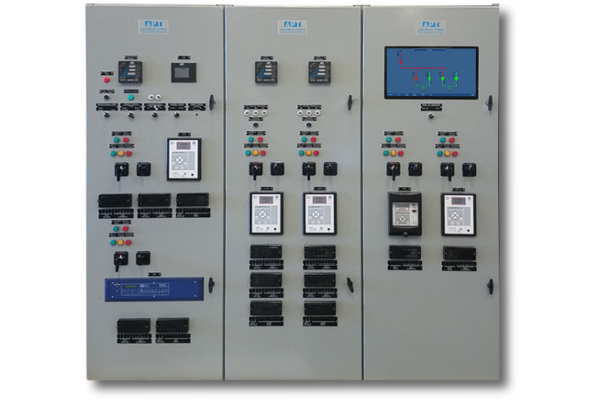
Switchgear transfer controls represent a crucial aspect of power management systems, enabling seamless transitions between different power sources. These controls play a pivotal role in ensuring uninterrupted power supply, especially in critical environments where downtime is not an option. By intelligently monitoring power availability and quality, switchgear transfer controls facilitate automatic or manual switching between primary and backup power sources, safeguarding against power outages. Their advanced algorithms and real-time monitoring capabilities guarantee a smooth transition, minimizing disruptions and maintaining the continuity of operations. From data centers to healthcare facilities, switchgear transfer controls provide the reliability and flexibility needed to manage power transfers efficiently, enhancing overall system resilience and ensuring optimal performance.
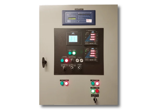
Automatic Standby Open Transition Transfer Control
Control switch is in “Auto” position:
Upon sensing of the utility failure (utility voltage is not within undervoltage setpoint), the Time Delay Engine Start timer shall start timing. If utility failure condition remains upon expiration of the Time Delay Engine Start timer, the generator set shall be automatically started and brought up to speed and voltage. At that time, the utility circuit breaker shall open and the generator circuit breaker shall close (after adjustable time delay neutral). The generator is then supplying power to the site load. Upon sensing of utility return (utility voltage is within set undervoltage tolerance), the Time Delay Emergency to Normal timer shall start timing. If utility power remains healthy (utility voltage is within set undervoltage tolerance) upon expiration of the Time Delay Emergency to Normal timer, the generator circuit breaker will open and the utility circuit breaker will close (after adjustable time delay neutral). At this time, the generator set will be put in the cool down mode of operation.
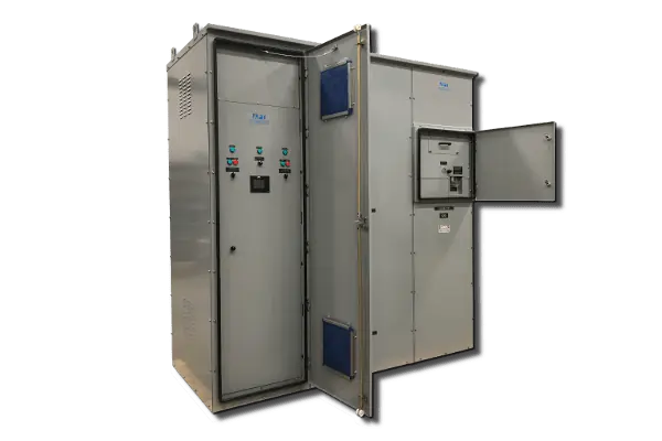
Time Delay Emergency to Normal timer is timing, that timer shall be bypassed, the generator circuit breaker shall open and the utility circuit breaker shall close (after adjustable time delay neutral).
Operation of the over-current protection shall trip generator and utility circuit breaker, and disable closing both circuit breakers until manually reset by placing the control switch in Off/Reset position.
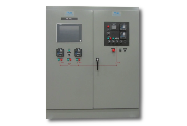
Automatic Standby Closed Transition Transfer
Control switch is in “Auto” position:
Upon receipt of an Isolate signal initiated locally by the operator or remotely by customer SCADA or DCS system (via closure of a dry contact or MODBUS TCP/IP), the switchgear shall verify that utility phase voltages and frequency are within acceptable tolerances, and issue a start signal to the generator set. At that time, the switchgear shall control the generator set’s speed and voltage.
The generator set’s voltage shall be automatically matched with the utility bus. The genset shall be automatically synchronized with the utility under the synchronizing check relay’s supervision. The synchronizing circuit breaker shall close once all synchronizing conditions are met. At that time, the generator set shall be gradually (soft) loaded to assume the entire site load (entire site load minus adjustable “zero power level” setpoint) and utility circuit breaker shall be tripped open. At this time, the site load has been transferred to the generator power.
Upon receipt of an automatic stop signal initiated locally by the operator, or remotely by customer SCADA or DCS system, the generator shall be synchronized with the utility source. Close the utility circuit breaker once the synchronizing check relay determines the generator and utility source are in sync. Soft unloading of the generator set shall then begin. When the genset load is gradually reduced to the level of the unload trip setpoint, the generator synchronizing breaker shall trip open, and the genset shall be put in the cooldown mode of operation. The site load should then be transferred to the utility power.
Loading and unloading rates and “zero power level” setpoints shall be viewable and adjustable from the operator interface panel mounted on the control panels front door.
ATC with Soft-loading/Unloading Control
Control switch is in “Auto” position:
Upon receipt of an automatic start signal initiated locally by the operator or remotely by customer SCADA or DCS system (via closure of a dry contact or via MODBUS TCP/IP ETHERNET interface), the switchgear shall verify that utility phase voltages and frequency are within acceptable tolerances, and issue a start signal to the generator set. At that time, the switchgear shall control the generator set’s speed and voltage.
The generator set’s voltage shall be automatically matched with the utility bus. The genset shall be automatically synchronized with the utility under the synchronizing check relays supervision. The synchronizing circuit breaker shall close once those are all in sync. At that time, the generator set shall be gradually (soft) loaded to the desired active and reactive loading levels, and remain at those levels until signaled to unload.
If the unit is signaled locally by the operator or remotely by customer SCADA or DCS system to operate in Import/Export control mode of operation, the desired utility kW contribution to the site load (import) or generator kW contribution to the utility grid (export) shall be automatically maintained.
Generator set loading (kW) setpoint, Import/Export setpoint, reactive power (kVAR) setpoint, loading and unloading times and loading dynamics setpoints shall be viewable and adjustable from the operator interface panel mounted on the control panel’s front door.
The switchgear shall constantly monitor utility bus to ensure constant presence of the utility at the utility side of the generator synchronizing circuit breaker. The utility intertie protection (included in the switchgear) shall sense if there is a severe fault on the utility side of the generator synchronizing circuit breaker, as well as operation of the upstream distribution recloser, or any other disconnection of the generator set from the utility upstream from the generator synchronizing circuit breaker. Upon sensing of any of the above conditions, the utility incoming circuit breaker shall immediately trip open and the generator set shall continue supplying power to the site load.
Upon receipt of an automatic stop signal initiated locally by the operator or remotely by customer SCADA or DCS system (via closure of a dry contact or via MODBUS TCP/IP ETHERNET interface) the switchgear shall gradually (soft) unload the generator set. When the genset load is reduced to the level of the unload trip setpoint (adjustable from the operator interface panel mounted on the switchgear door), the generator synchronizing breaker shall trip open. The genset shall be put in the cooldown mode of operation.
