DataCTR - Data Center Power Systems
Automatic Transfer, Generator Paralleling, & Power Distribution Switchgear & Switchboards for Large Data Center Systems
APT has the resources and expertise to provide safe, reliable, and cost-effective solutions for the redundancy required for up to Tier 4 data center backup. That includes redundancy applications, especially for data center switchgear.
No matter the size or difficulty level of the site, we have you covered from the incoming utility, down to distribution and all the redundancy in between:
- Data Center Site Planning, One-Line Diagram Development, Engineering and Design Review
- Outdoor Walk-In Automatic Transfer & Distribution Switchgear Modules with sheltered working and maintenance rooms
- Remote Monitoring SCADA systems
- Pole Mounted or Pad Mounted Low and Medium Voltage Gang-Operated Disconnect Switches, Fuses, Surge Arresters, and Cut-Outs
- Low and Medium Voltage Utility Intertie Switchgear according to IEEE 1547 and Utility Company requirements
- Transient Voltage Surge Suppression
- Outdoor NEMA 3R Non-Walk-In
- Advanced controls for peak shaving, paralleling with utilities, generators, & islanding
- Valve Regulated Lead Acid Energy Control Power Systems
- Low to Medium Voltage Step-up & Step-Down Transformers
- On-site Commissioning Assistance, Training, Troubleshooting & more!
Data Center Switchgear
Power Quality Metering & Utility Intertie
- UL recognized for Advanced Power Metering
- True RMS, 3 Element Power Quality Metering:
- Metering accuracy shall be in accordance with ANSI C12.20-1998, rated an with accuracies as follows:
- Class 10 0.5% for energy.
- 2% of reading and 0.02% of full scale for voltages and currents.
- 3% of reading and 0.02% of full scale for active and apparent power
- Dedicated high-brightness digital LED displays are visible in the bright sun light or in the dark
- Metering accuracy shall be in accordance with ANSI C12.20-1998, rated an with accuracies as follows:
- Environmental Conditions
- Operating temperature:
- -20°C to 60°C (-4°F to 140°F)
- Humidity:
- 0 to 95% non-condensing
- Operating temperature:
- Service Entrance Utility Intertie Options
- IEEE 1547 – IEEE Standard for Interconnecting Distributed Resources with Electric Power
- Visible circuit disconnect with draw-out main circuit breaker
- Utility Intertie Protective Relay Functions as required
- Voltage & Current Test Switches per utility requirements
- Potential Transformers (PTs):
- Fused, revenue grade potential transformers connected in wye or delta configuration
- Current Transformers (CTs):
- Dedicated Revenue Grade CTs with 0.3% Accuracy @ B0.1 Burden for Revenue Grade Meters as required
What is Redundancy?
Redundancy refers to the inclusion of backup or duplicate components, systems, or configurations to ensure the reliable operation of the switchgear in case of component failures or other unforeseen events. Redundancy is a critical aspect of switchgear design because switchgear controls electrical power distribution and control. Failures in switchgear can lead to power outages, equipment damage, and potentially hazardous situations.
Parallel Switchgear:
- Parallel switchgear configurations involve the use of multiple identical switchgear assemblies operating in parallel. If one switchgear assembly fails, the others can continue to supply power, minimizing downtime.
Remote Switching:
- Some switchgear designs incorporate remote switching capabilities, allowing operators to switch between redundant components or systems from a safe distance without physical intervention.
Backup Sources:
- In some cases, switchgear may have provisions for connecting to backup power sources, such as emergency generators or uninterruptible power supplies (UPS). These backup sources ensure power continuity in the event of a primary power failure.
Maintenance Bypass:
- Redundancy can also be achieved by designing switchgear with maintenance bypass features. This allows for the isolation and replacement of faulty components without interrupting power to critical loads.
Fault Tolerance:
- Fault-tolerant designs incorporate redundancy to maintain operation even in the presence of faults, such as short circuits or component failures, without causing a complete system shutdown.
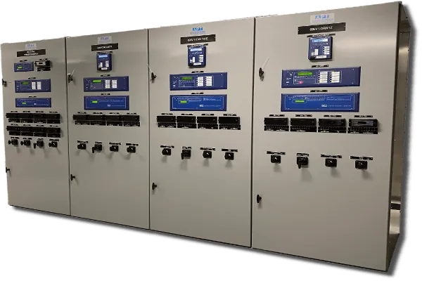
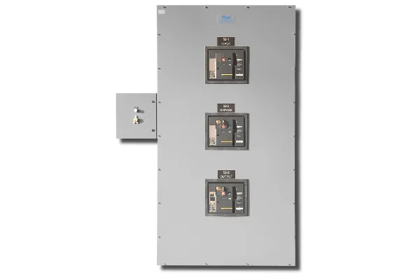
Low Voltage Data Center Switchgear/Switchboards
SBU-Series
- 208V – 690V, 3Ø
- Silver plated copper bus
- Standard bus ampacity up to 4000A
- Bus Access & Cable Entry
- Front or Rear Access for either top or bottom cable entry
- Your choice of Insulated Case or Molded Case Circuit Breakers
- Intelligent close prevents simultaneously connecting multiple generators to dead bus with adding APT Generator Paralleling Modules to generator circuit breaker sections
- NEMA 1 (indoor) or NEMA 3R (outdoor) Non-Walk-In
- Integrated into APT PwrContainer ISO Container Based Outdoor Walk-In Switchgear Enclosure Module
- Click here to learn more about our SBU-Series
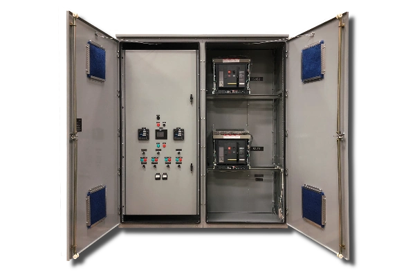
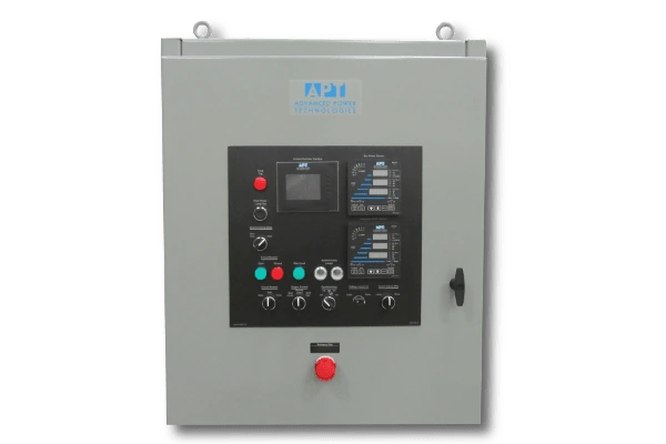
Automatic Transfer with Bypass
- 208V – 480V
- Automatic Transfer Switchgear with Bypass Isolation
- Automatic Transfer Overview:
- If there is a total loss of utility power, automatic transfer mode will cause the generator to automatically start. The generator will then come on-line and assume site load.
- After utility power returns, a sequence of functions may be executed to return the breakers to their normal positions in an open transition.
- After the return to normal, the generator(s) automatically come off-line, cools down, and is ready for the next start.
- Manual Control Overview
- Automatic Transfer Overview:
- Provides independent electrical fault protection for all sources:
- 27/59 – Three-phase under/over voltage
- 81O/U – Over/under frequency (Optional)
Bypass/Isolation
- 208V – 480V
- UPS Maintenance Bypass/Isolation with Manual, Non-electric Kirk Key Operation:
- Three identical Kirk Key locks with two identical Kirk Keys allow for only two circuit breakers to be closed at the same time.
- Remove key from source 1 and insert into the bypass circuit breaker. This enables source 2 to provide power to the load normally served by source 1.
- Works best in Generator & UPS applications
Solenoid Key
- UPS Bypass/Isolation with Solenoid Key Release Unit (SKRU):
- SKRU with A-1 Key held captive
- UPS output breaker A is closed supplying the critical load through the UPS
- Key B-1 is held captive in the L-O interlock on breaker A
- Maintenance bypass breaker B cannot be closed until the UPS is placed in bypass mode
- As a result, this sends a signal to the SKRU allowing release of key A-1
- The SKRU has an apartment lock that will accept either key A-1 or B-1
- See Page 11 of the DataCTR Brochure to learn how to supply critical load through the maintenance bypass breaker
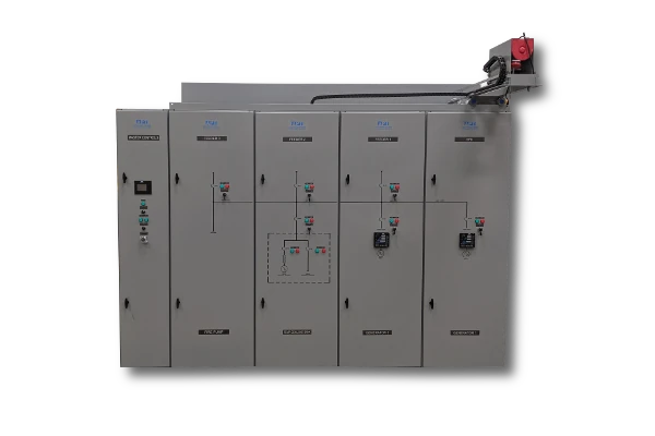
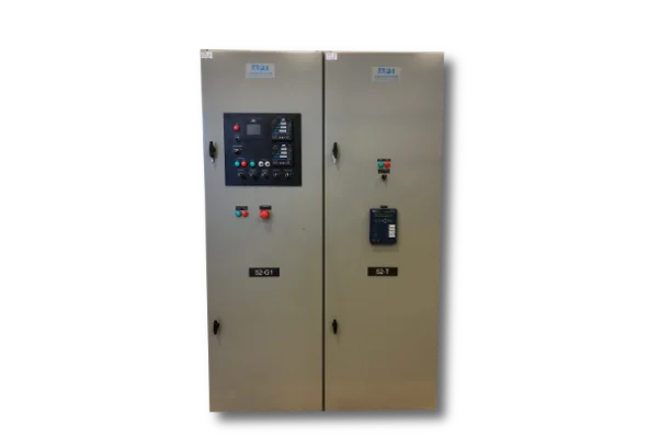
Generator Paralleling & Control Sections in Plant Power Distribution Systems
- Behind door mounted generator protection circuit breaker provides an added layer of operator protection
- Can automatically parallel multiple generators in the same or multiple sections
- Complete manual paralleling facilities
- Complete 3Ø Generator Protection
- Remote Start/Stop Interface
- Prevention of closing of multiple generators to a dead bus simultaneously
- Even more features!
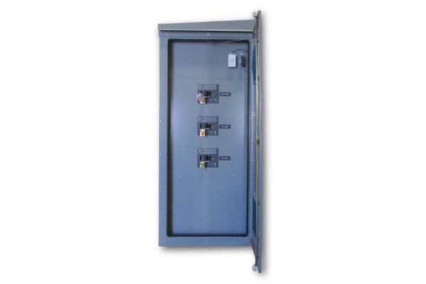
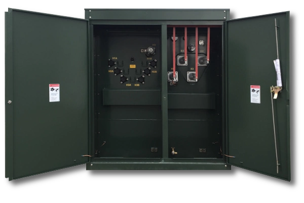
Protection for Facility Main/Feeders in Plant Power Distribution Systems
- High visibility, LED type indicating lights with a service life of 100,000 hours at 77°F
- Your choice of Molded Case or Insulated Case Circuit Breakers
- Circuit Breaker Trip Units:
- LI – Adjustable long time, instantaneous trip settings
- LSI – Adjustable long & short time, instantaneous trip settings
- LSIG – Adjustable long & short time, instantaneous trip settings, with ground fault trip settings
PTX-Series Utility Power Transformers
- Built for easy transportation, installation, and rapid power deployment applications
- Low to Medium Voltage
- High Voltage Side:
- Aluminum windings
- 2.4kV – 34,500 V Delta or Wye Connected
- BIL up to 200kV
- Live front
- Radial feed
- Low Voltage Side:
- Aluminium windings
- Single Low Voltage winding
- 208V – 1200 V Delta or Grounded Wye Connected
- BIL up to 60kV
- Epoxy 2 piece-bushings with 4-holes blade
- Pad Mount, Step Down
- Ratings:
- 500kVA – 3,000 kVA
- Frequency: 60 Hz
- Impedance: 5.75% ± 7.5%
- Temperature Rise: 65°C
- Dead front or Loop feed options
- Enclosure:
- Outdoor NEMA 3R
- Mild steel tank & cabinet
- Powder paint system; Color: ANSI 70 or Green Munsell 7GY 3.29/1.5
- Weights: 7000 – 17,500 lbs.
- APT FAC-Series front access compact low and medium voltage air insulated switchgear is the ideal switchgear for this transformer
- You can find more on the PTX-Series Dry Type & Oil Filled Power Transformers here
Product Literature
WE ARE HERE
TO SERVE YOU
We are committed to providing expert support and tailored power solutions. Contact our team today to find the right answers for your words.