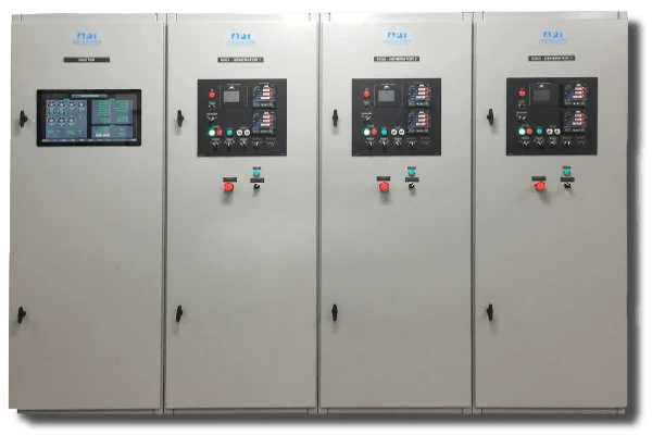
Powering Life for Modern Humanity

GP - ACM Generator Paralleling

Generator Automatic Paralleling Controls & Switchgear Equipment

Previous slide
Next slide

APT switchgear with GP paralleling control system modules allow for easier maintenance. It also creates better operator experience. APT generator automatic paralleling switchgear control modules are located in a controlled environment, removed from the dangers and vibrations of rotating machines. Our generator paralleling switchgear is open architecture. In other words, it allows for use with multiple genset manufacturers. APT’s generator automatic paralleling switchgear control has greater flexibility; it has operation modes that can be achieved and future expansion capabilities.

GP Generator Automatic Paralleling Switchgear Control

Core Competencies

  • Our engineers with decades of experience in the field of generator paralleling have developed this control module
  • Product line continuity, as electronic components become obsolete and new features are added
  • We provide the project support and version control for the life of the generator switchgear installation and beyond. We retain all project records indefinitely

Automatic Paralleling Switchgear Features

  • Can be used in Prime Power or an Emergency Power application. This requires operating multiple generators in parallel
  • Available in Low Voltage (UL891 listed) or Medium Voltage (UL Metal Clad)
  • Integrated Microprocessor Control
  • Completely automatic operation
    • Automatic Paralleling
    • Remote Start/Stop Interface
    • kW and kVAR Load Sharing
    • Load Shed Control
  • Optional SCADA-ready Modbus Comm Port for Monitoring and Control
  • Standard Silver Plated Copper Bus
  • Inhibits Closing Multiple Generators to a Dead Bus Simultaneously
  • First Up – First On Logic Connects First Available (which builds up voltage and frequency) to a Dead Bus
  • See page 3 of Generator Paralleling Control Module Brochure for more features
Automatic paralleling Switchgear Control Panel
GP-ACM-Generator-Paralleling-Control-Module-APT-Power-2-Generator-Automatic-Paralleling-Switchgear-Control

Single Generator Control Panel Specifications

Voltage Inputs

  • 208 – 690V, direct 3 phase sensing
  • Above 690V, sensing from switchgear PT’s
  • Input Impedance: 1000 Ω 
  • Voltage withstand: 1000 VAC continuous, 2000 VAC for 1 second

Current Inputs

  • 0-5 Amp sensing from generator or switchgear CTs
  • Operating range: continuous 10A RMS
  • Burden: < 0.2 VA @ In=5A
  • Withstand: 15A RMS continuous, 300A RMS for 1 second

Sampling Rate

128 samples/cycle

Electromagnetic Immunity

ANSI/IEEE C37.90.1:

Fast Transient SWC

Metering Accuracy

  • Per ANSI C12.20-1998:
  • Class 10 0.5% for energy
  • 0.2% of reading and 0.02% of full scale for voltages and currents
  • 0.3% of reading and 0.02% of full scale for active and apparent power

Generator Metering

True RMS, 3 phase

(A, V, Hz, kW, PF, kVAR, kWh, kVARh)

Bus Metering

True RMS, 3 phase

(A, V, Hz, kW, PF, kVAR, kWh, kVARh)

Generator Protection

  • Three phase under/overvoltage
  • Under/over frequency
  • Reverse power (two setpoints)
  • Reverse VARs (two setpoints)
  • Current balance (two setpoints)
  • Overcurrent protection provided by generator output or switchgear circuit breaker

Optional Bus Protection

Three (3) phase under/overvoltage and under/over frequency

Generator Set Governor & AVR Interface:

0-10 V, +/-10 V, 4-20 mA, microprocessor controlled potentiometer

Metering Displays

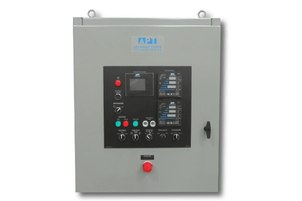
Dedicated high-brightness digital LED generator and bus metering displays visible in the
in the bright sun light or in the dark

APT-Power-GP-Generator-Automatic-Paralleling-Switchgear-Control

ACM Series Control System Requirements

  • Engine-Generator set with engine control module (Caterpillar ADEM, EMCP or similar) and generator voltage regulator, capable of voltage droop operation
  • Electrically operated generator circuit breaker with stored energy mechanism
  • Circuit breaker control power source
  • Generator CTs for generator metering and protection functions
  • Generator and bus PTs for systems above 690 Volts

Switchgear Integration Options

  • System Voltages:

    208 – 600V, 3 phase, 3 or 4 wire
    2.4kV – 15kV, 3 phase, 3 wire
  • Current:

    Up to 4000A UL listed (low voltage)
    Up to 10,000A Non-UL listed (low voltage) Up to 3000A UL listed (medium voltage)
  • Enclosure:

    NEMA 1 for indoor use, wall mount or floor standing NEMA 3R for outdoor use, wall mount or floor standing
    Stainless Steel, wall mount or floor standing Switchgear Door Mountable

   Operation Overview

Upon receipt of an automatic start signal initiated locally by the operator or remotely by customer’s SCADA RTU (via closure of a dry contact), the switchgear shall issue a start signal to the generator set. At this time, the switchgear shall control the generator set’s speed. Generator voltage shall be determined by the voltage adjust potentiometer. If the bus is dead and other conditions are appropriate, then the first generator to build up voltage and frequency shall close its synchronizing circuit breaker. This energizes the bus, as a result. If the load bus is already energized, then the generator set shall be automatically synchronized with the load bus under the supervision of the dedicated synchronizing check relay. 

The synchronizing circuit breaker shall close once all synchronizing conditions are met. At this time, the generator set shall operate as an isochronous load sharing machine. Real load (kW) and reactive load (kVAR) shall be shared proportionally with other generator sets connected to the load bus.

Upon receipt of an automatic stop signal initiated locally by the operator or remotely by customer SCADA or DCS system (via closure of a dry contact) the switchgear shall automatically open the circuit breaker and shutdown the generator set after a cool down period.

The switchgear shall also include provisions for manual operation.

Load Shed Control Equipment

In case of bus overload, multiple stage load shed capability shall be provided. Non-critical loads feeder circuit breakers shall be tripped and/or form “C” dry type contacts. They will be provided for each stage of load shedding to disconnect non-critical loads downstream from the switchgear.

Load shed ON – OFF/RESET switch shall be provided as part of the system.

Time delays for each stage of load shed shall be adjustable through the operator interface unit mounted on the door.

Engineering Bid Specifications

Installation Drawings & Diagrams

Coming Soon!